Introducing PSoC
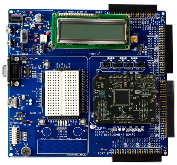
After a long period of silence I am finally back to business. Two months ago I have ordered a Cypress CY8CKIT-001A development kit for PSoC 1/3/5 (at the picture). Unfortunately the first board arrived DoA so the whole RMA and reorder took some time. The second board fortunately is working fine.
The main board features are:
– PSOC 1/3/5 compatibility
– USB connectivity – and that one was the most important for me
– RS232
– CapSense touch buttons + slider
– potentiometer
– 1602 LCD
– breadboard area
It might miss few things but for a bit less than 300EUR is a really good value for money.
So for the last week I was learning how to program the PSoC3. Starting from the very basic tasks and later on moving to the ADC or CapSense. The target is to start with USB development. Also thanks to the programmable digital logic on the chip the Verilog language has made into my list of “to do”.
The PSoC3 delivered with the kit is a ES2 version. Cypress promised to replace that engineering sample with a normal one. Good job. I would never expect that so I was really happy to hear about it.
PS/2 to RS232 bridge
For the project that I will present within the next two weeks I need a way to debug the PS/2 transmissions. The easiest way would be to simply connect to the cable using the logic analyser but I don’t have one so I used a different approach. As shown in my previous post I wrote a RS232 TX. Later on I added a PS/2 receiver to it. This works and allows to debug the PS/2. The total time spent for development and testing sums up to 12 hours.
RS232 transmitter
For almost a year I had a Spartan3E starter kit waiting for the right moment. I bought it to use it for LabVIEW FPGA and for some Linux projects. Since the LabVIEW FPGA took me only a little time the board was catching dust since then. Now I have an idea how to use it. In the last few days I refreshed my VHDL and went through the manual for Xilinx ISE environment once again. The first module that I need is a RS232 TX. I did not wrote such core in few months so it took me two hours to make a first test core. It sends out the predefined byte once per second. I verified the core yesterday and it works (19200baud, 8N1). There is no part that will stay unmodified and some other elements will be added (as bit reordering). The project is pure VHDL, no schematics or anything like that.
9201 a second compact module has arrived
I recently bought a used NI 9201 module. That is a 8 channel 12-bit analog-to-digital module that has an aggregated sample rate of 500ksps. I will perform the functional test of the module by Wednesday but it passed the self test so I don’t worry about it. I plan to use the module for data acquisition in my spectrography project. It will sample the voltage generated by the photodiode and perform low speed sampling on other sensors such as temperature sensor (preconditioned).
Now my laboratory has a new item and I really hope I will be able to get one of the cRIO chassis on e-bay 🙂
And speaking of the current project – I have a request for verification the 500-530 nm waves transmission/reflection. This made me to look for some informations on spectrography. The first design is just a concept. I will make a spectrograph using diffraction grating and LED as a source. Using semiconductor parts that emit or detect a narrow band of spectrum can significantly simplify the equipment.
Configuration/settings/options dialog in LabVIEW
For a long time I used the default LabVIEW dialog templates to build my own configuration/options/settings dialog. Of course they are really useful when the program is small and require just several parameters. The problem start at the moment when the number of parameters grows. At that point the dialog which holds the settings becomes unclear and overloaded with information. Everyone should try to reuse the best solutions of other systems and port them to LabVIEW. I’ve decided to make a dialog that can hold the application settings in the form similar to the one that pops up when Tools->Options is clicked (in LabVIEW, screen-shot is presented below).
So this is the layout that I copied. The original dialog uses a list to show the categories. My VI has a tree control so the designer can use branches to clear up the whole view. The drawback is that the easiest event to detect was the doubleclick so the category is changed that way. It shouldn’t be hard to detect a single click but I did not want to add much code. This way it is just the UI plus a simple algorithm to change pages. The LabVIEW UI shown below is built around three splitter bars that create four areas. One area for the ok/cancel/help buttons, one for the tree control that holds categories, one area for the top label with the name of the active category and one area for the tab control which holds the settings controls.
National Instruments page has a communities section. One of the communities addresses the UI (UI Interest Group). I published the VI there so you can download it and give it a try.
Power Point or….? Beamer!
Since I read the Doxygen tutorials I planned to prepare a presentation for my colleagues. For many years I used the Power Point, but now I am really disappointed. The latest version 2010 is worse than the previous ones. Not so long ago I spent few days to make a presentation about UI upgrade of one of my programs. At the end I applied the theme and the presentation just didn’t look good. Microsoft added a lot of fancy themes to the latest edition but all the traditional ones are no longer available (at least in the vanilla installation). Maybe they are on the internet but I want to have them immediately available and not to look for them at the MS site. All that pushed me to look for something different. The Doxygen has an option to export the documentation in LaTeX format. I learned a bit of LaTeX last year when I prepared my thesis at the postgraduate studies. So now I use Beamer. There is a great introduction to it at http://www.math.umbc.edu/~rouben/beamer/ also the Not so short introduction to LaTeX is useful during the preparation of the slides. I will post the completed presentation next week.
Another tool that is worth looking at is the beamerposter class. I am preparing a poster that presents my achievements. My first idea was to simply prepare a leaflet but if I have all the information in plain text then I can simply produce a nice looking poster. The only drawback of the beamerposter is that there is no tutorial for it. But there are examples and if you know LaTeX and Beamer then this is no big deal to sit down and learn from them.
Doxygen
At the moment I am ready to restart one of my projects that I will describe in details later on. Cutting it short – it will use an ARM Cortex-M3 microcontroller with USB connectivity. One of my concerns is the documentation of the code that will write as it might happen that someone will need to modify my code in future. I also have a similar situation at work so I’ve decided to look for an open source program that can auto-generate the documentation from C language code. After a short search I found Doxygen which can create a documentation from C,C++,C#,PHP,Python,VHDL and some other languages. The comments in the code need to be adapted to work with it but it doesn’t take much time and after some time it is done automatically. The documentation is good and most of the tutorials are listed at the Doxygen page (http://www.doxygen.nl/articles.html). I just spent a short amount of time reading the documentation but I see that I will probably use it as it suits my needs. I really like the layout that is created in the HTML. You can see it on a picture below, and it took me only minutes to create a dummy code and run documentation generation on it. Actually I think I will prepare a short presentation for my co-workers so they can give their opinions about it. A description from the daily work with Doxygen (and maybe the presentation if I will prepare it) will follow.
Slider
Finally I made the slider board for the STM8-Discovery evaluation board. It took me almost 4 days to finish. I used the Eagle EDA software to design it. The Eagle might have a steep learning curve but after two days I am finally done with it. I did not want to do the schematic so I just went directly to layout editor and designed the board. The slider for STM8 Touch Sense Library can have 5 or 8 sections and its parameters are defined in the AN2869 application note. A figure from it is presented below.
I planned to view the board in 3d as I did previously with the KiCad and Altium Designer. Eagle does not support such views by default. Fortunately one can find a package for using pov-ray to render the board on the internet. The outcome you can see below.
Manufacturing the board at home was easy as I have all the necessary equipment already set up. The finished board you can see below. The soldering was a bit tough as I did it at 5 o’clock in the morning so it isn’t the best I’ve done (actually it is awful). The dielectric cover is a piece of microSD card package (they come in a big piece of plastic that you usually throw out immediately- so now there is a reason to leave them for future use). The piece of plastic was glued to the PCB.
Nevertheless the board was verified electrically and then tested with STM8-Discovery. The best way is to connect the slider, configure the library and watch the position variable to see if it is properly set. The ST Visual Develop allows to use real time updates on the watch window. This allows to quickly verify the design.
One issue that I saw are those two slider pad halves at the beginning and at the end of the slider. The documentation does not define how they should be connected. The configuration file also does not clarify the situation and I think it would work better with all 5 pads of equal size. I will send a question to ST-Microelectronics and post the answer later.
Touch Sensing Library in STM8
It took me a while to get everything up and running with the STM8S-Discovery board. The board is nice and cheap, the tools are a bit awkward (especially if one compare them to the tools that can use for PC development) but they are ok. One thing that is missing is the documentation. The papers which are on the ST page are lacking some basic informations and some are even outdated (watch out on the zip files that contains several libraries). The support from the community don’t exist at the moment so one thing that came to my mind was to browse the internet.
A proper tutorial on how to use the firmware supplied by the ST can be found on Ben Ryves page: http://benryves.com/journal/3567231
The people in ST should learn form him (at least about how the app notes for starting with their firmware should look like).
Going through the tutorial took me several hours and finally all was working as it supposed. It was a time to design my own touch button. ST has two app notes on the design for touch sensing panels.
– AN2869 – Guidelines for designing touch sensing applications
– AN2927 – RC acquisition principle for touch sensing applications
Those app notes are enough to design a working button but they lack some explanations. A good point to get under the hood might be the Atmel page and their app notes.
For the board design I used Altium Designer. Last time that I worked with it was like 3 years ago so I had to go through the tutorial again. The basics didn’t change so it was not painful at all. The first board that I manufactured was incorrect and I had to develop my own set of constraints for home made PCB. Below you can see the schematics and the 3d view of the board (oh, and Altium probably can import the VRML so I can use the Wings 3D to do the parts models).
This board isn’t the best one and I would change few things there but it works so there is no sense to update the project. The code for the microcontroller was the same as the one which is in the tutorial with a small change in configuration of the TSL. I used port B to connect the touch button. You can see the assembled touch key module below. It has a size of approx. 30×20 mm. The button cover is made out of a part of a plastic CD cover (I need to find a better solution for that as it is hard to cut it as it cracks when you try to do something with it).
When assembling the board I did not connect the shield. I did not want to modify the design as it was only a matter of soldering a joint and not soldering a resistor so I defined an assembly variant in the project. I have to say I am impressed how the Altium is constantly adding new solutions to the Designer and keeps the mainstream untouched (the use of the program is exactly the same as the DXP I used few years ago).
The next stage is to develop the slider and maybe a wheel. I will design the boards to be used with STM8 and then I will wait for the new Altium Designer for year 2010. It will include a module to lay out the capacitive buttons for the Atmel QTouch library and devices. I will postpone the part with the HW controller solution until it will be released.
QFN package (RGB led driver IC)
After making some research on the QFN packages I found out that there is no way to solder them with traditional soldering station. The hot air is a must. It took me almost a day to view all posts about the hot air stations on edaboard. The outcome is brutal – I can afford a Chinese one, and the better one is still a bit pricey.
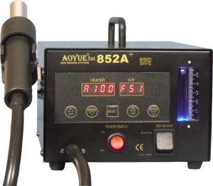
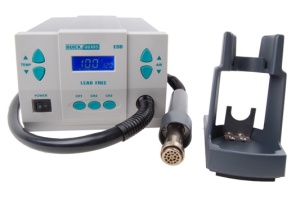
The first model is known under many names. It is the AOYUE 852/852++ station. The second one is also Chinese. A Quick 861DS ESD. If you take a look at the pictures below you will see the difference immediately.
If one would do a quick comparison of both of the soldering stations then some obvious differences would be seen. And those are: the heater in Quick is 1kW compared to 270W, real temperature stabilisation (see it on you tube), brushless motor and a standby mode is making Quick superior to the AOYUE. The main advantage of AOYUE is the price which is 1/3 of the Quick price (for the analog controlled station, the digitally controlled station from AOYUE is 1/2 of the Quick price). Also the accessories price is different and the Quick accessories are 3 times more expensive than those for AOYUE (although one can use an adapter to use the cheap accessories). Which one I will choose is still unknown.
Getting back to QFN packages. There is a nice video about soldering such packages from Curious Inventor: http://www.youtube.com/watch?v=c_Qt5CtUlqY
One can also find a document from Intersil which contains guidelines about the QFN packages: http://www.intersil.com/data/tb/TB389.pdf
I think that material shows how to live with such IC packages and as a final word I have to say that I’ve decided to buy the Quick hot air station. Of course it is two times more expensive but I will be using it for quite some time and I do not plan to buy another one in next five years.


